HFC Twin Screw Compressor Pack – Case Study
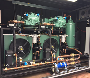
HFC Twin Screw Compressor
Project Brief:
- Spiral Freezer
- Product – Sausages
- Total Cooling Load – 82kW Evaporating at -40°C.
- Total Cooling load to be split across two Screw Compressors.
- RDM Control.
- EC Condenser Fans.
- Packs to be externally mounted.
- Condenser to be Skid Mounted behind the pack.
Design
The client had specified that the compressors were to be Bitzer, so we started design by using the Bitzer selection software to choose the correct machines. This was sent to Bitzer to select and supply all of the additional oil management components (Oil Cooler, Separator, Filters etc.) along with instruction of the specific arrangement.
With the size and height that the pack would need to be to ensure the correct oil management, we knew that it would not fit in any of our standard housings. We designed a bespoke pack frame and liaised with our housing supplier to obtain a suitable housing and skid solution.
To minimise the compressor size and improve efficiency, the selection was made using a sub-cooling economiser in circuit. The compressor selection details the requirement allowing us to make a plate heat exchanger selection, along with the associated expansion valves.
We now had all the information that was needed to select the condenser, and start the build.
Build
Upon the arrival of the pack frame we were able to get all the main mechanical components in place, paying particularly close attention to the height of the oil separator in relation to the compressors to make sure we had good supply of oil. This allowed us to pipe the main components together while we were waiting for the housing to arrive. We also took the decision to include a three way oil mixing valve in to the oil circuit to ensure that the correct oil temperature was maintained at all times. This valve mixes oil straight from the oil separator with the oil leaving the ‘oil cooler’ to maintain an optimum temperature.
Once the housing and skid had arrived the pack was lifted in to place ready to be wired.
In the meantime, we joined two of our standard, three fan condenser blocks together and created a header to allow the two coils to work as one. We bolted legs on to the finished assembly and fitted it to the unit.
Evaporators and Pipe work
The evaporator and interconnecting pipework had been supplied by the client and did not form part of our scope. We did however check them over on site during the installaton to give the client guidance on the system set up.
On Site Support and Maintenance
We ensured that the install teams and client had all the support they needed and made sure we were present to assist with the set up and commissioning of the system.
Particular care was given during design and build to ensure that parts requiring regular maintenance were accessible.
Plant Costs
Whilst the plant cost was slightly higher than a more standard reciprocating solution, with the lower evaporating conditions, and fixed load the client had specifically requested screw compressors.
Efficiency
The oil cooler and condenser fans are both speed controlled EC motors and the compressors both have unloaded start capability and capacity control (50/75/100%). This gives range from 82kW down to 20kW allowing the pack to match and balance the spiral chiller load depending on its operation.
Legislation
The plant was designed initially to run on a higher GWP HFC refrigerant at the clients request with a view to it being dropped on to a more environmentally friendly one in the future. Calculations were carried out on R448a, R452A and R449a to ensure its future operation. From January 2022, under F-Gas Law, this installation would have had to use a refrigerant with a global warming potential lower than 150 as it exceeds 40kW and evaporates above -50°C.